How Does Power Flow Through a Data Center? – Utility to Rack

A server rack does not plug into the grid. Between the transmission line outside the fence and the power supply inside each server, electricity passes through a long chain of transformers, breakers, batteries and cables, and each link changes the voltage, adds protection or adds a backup path. Trace that chain once and a lot of data center design suddenly makes sense. How does power actually flow through a data center, from the utility all the way to the rack?
Data center power distribution follows a chain: utility power arrives at high or medium voltage, transformers step it down to 480 volts, switchgear routes it through generator backup and a UPS, and power distribution units deliver it to racks at 208 to 415 volts, where server power supplies convert it to low-voltage DC.
Generators cover outages, the UPS bridges the seconds in between, and many sites run two independent paths (A and B) to every rack. Each conversion loses a little energy as heat. In a typical design, roughly 10% to 15% of the power entering the chain is lost before it reaches the server's internal electronics, depending on equipment efficiency.
How Does Power Flow Through a Data Center?
Here is the whole chain at a glance, for a typical North American facility:
- Utility transmission or distribution line, at 12 to 345 kilovolts (kV).
- Substation or service entrance, stepping down to a campus medium voltage such as 13.8 kV.
- Medium-voltage switchgear and cables feeding each building.
- Unit substations stepping down to 480 volts, with generators and transfer equipment for backup.
- Uninterruptible power supply (UPS) systems conditioning power and bridging outages.
- Power distribution units (PDUs), remote power panels or busway, delivering 208 to 415 volts.
- Rack power strips and server power supplies, converting AC to the low-voltage DC that chips use.
Step 1: Utility Service and Substation
Data centers are heavy users. The U.S. Department of Energy notes that data centers use 10 to 50 times the energy per square foot of a typical office building, so even modest facilities need a dedicated service.
Small sites take power from a utility distribution feeder at 12.47 or 13.2 kV. Large campuses connect at transmission voltage, often 69 to 345 kV, through a substation with large power transformers. Many facilities ask for two utility feeds from different substations so a single line outage does not force a generator start.
Step 2: Medium Voltage and Unit Substations
From the substation, medium-voltage switchgear and shielded cables carry power across the campus. Medium voltage keeps the current low: at 13.8 kV, a feeder carries about 1/29th the current it would at 480 volts for the same power.
Near each load area, a unit substation steps 13.8 kV down to 480Y/277 volts. Typical unit substations in data centers range from about 2,000 to 3,000 kilovolt-amperes (kVA). Their low-voltage switchgear is often arranged as main-tie-main, so either of two transformers can carry the whole load during maintenance.
Step 3: Generators and Transfer
Backup generators connect at this level, either at 480 volts beside each unit substation or at medium voltage on a paralleling bus. When the utility fails, transfer equipment (an automatic transfer switch or interlocked breakers in switchgear) starts the generators and moves the load to them, usually within about 10 seconds.
Some facilities go further and put on-site generation at the front of the chain, running every day instead of only during outages. If you are buying that kind of plant, the interfaces at this level, such as voltage, fault current, load steps and protection, are exactly what belongs in an on-site power RFP.
Step 4: The UPS
The UPS is the link that makes the 10-second generator start invisible to servers. Most large facilities use double-conversion units, which turn incoming AC into DC, keep batteries or a flywheel on the DC bus, and rebuild a clean AC output. When input power fails, stored energy carries the load with no transfer gap. Our guide to the data center UPS covers batteries, flywheels and runtime.
Not everything rides on the UPS. Large chillers usually run on generator power only, while pumps and fans that keep cooling moving may have their own UPS.
Step 5: PDUs, Busway and Rack Power Strips
The UPS output, still at 480 volts, goes to power distribution units on the data hall floor. A traditional PDU contains a transformer that steps 480 volts down to 208/120 volts, then breakers that feed branch circuits to racks. Many newer designs use 415/240 volts instead: a 415-volt three-phase system delivers 240 volts from each phase to neutral, which servers accept directly, and that can remove a transformer stage.
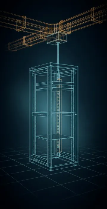
Power reaches racks either through cables from PDUs and remote power panels or through overhead busway with plug-in tap boxes, which makes it easier to add or move racks. Inside each rack, power strips (rack PDUs) distribute power to individual servers and often meter each outlet.
Step 6: Inside the Server
The server's power supply converts AC at 200 to 240 volts into low-voltage DC, typically 12 volts. Voltage regulators on the motherboard then step that down again to around one volt for processors and memory. Some rack designs instead convert power to DC once at the rack level, often at 48 volts, and feed servers from a shared DC bus.
How Much Power Is Lost Along the Way?
Every conversion wastes a small percentage as heat. The chart below follows 100 kilowatts (kW) through the chain using assumed, reasonable efficiencies for each stage. It is a model, not measured data.
Starting with 100 kW at the service entrance
Model: assumed efficiencies of 98.5% (step-down transformer), 95% (double-conversion UPS), 97.5% (PDU transformer), 99% (cabling) and 94% (server power supply). Illustrative, not measured data.
View the data
| Power remaining | |
|---|---|
| Service entrance | 100.0 kW |
| After step-down transformer | 98.5 kW |
| After UPS | 93.6 kW |
| After PDU transformer | 91.2 kW |
| After cables | 90.3 kW |
| After server power supply | 84.9 kW |
The math is a simple chain of multiplications: 100 × 0.985 × 0.95 × 0.975 × 0.99 × 0.94 ≈ 84.9 kW. In this model, about 15 kW of every 100 kW becomes heat before reaching the server's internal electronics, and the cooling system then has to remove that heat too. Swap in a 97% efficient UPS and drop the PDU transformer by using 415 volts, and the result rises to about 88.9 kW. That is why efficient distribution shows up directly in power usage effectiveness (PUE).
What Does A and B Power Distribution Mean?
Most enterprise and colocation servers have two power supplies and two cords. In a dual-path design, the A cord connects to one complete chain (UPS, PDU, rack strip) and the B cord to a separate one. If anything fails on the A side, the B side carries the server alone.
In a full 2N design, each side is sized for the entire load, so each normally runs at no more than half its capacity. Distributed redundant designs share spare capacity across three or more paths instead, saving equipment at the cost of more careful load management.
The weak points are the places where paths come back together, and single-corded equipment, which needs a static transfer switch or rack transfer switch to benefit from two sources.
What Voltage Is Used at Each Stage?
The table collects the typical North American values in one place. Exact voltages vary by utility and by design.
| Stage | Typical voltage | Main equipment |
|---|---|---|
| Utility supply | 12.47 kV to 345 kV | Lines, substation, power transformers |
| Campus distribution | 4.16 kV to 34.5 kV | Medium-voltage switchgear and cable |
| Building distribution | 480 V three-phase | Unit substations, low-voltage switchgear, generators |
| Critical power | 480 V or 415 V | UPS systems |
| Rack feed | 208/120 V or 415/240 V | PDUs, remote power panels, busway |
| Inside the server | 12 V DC, then about 1 V | Power supply and voltage regulators |
How Is the Power Chain Monitored?
With meters at nearly every link. An electrical power monitoring system collects readings from relays and meters in the switchgear, the UPS controls, PDUs, busway tap boxes and rack power strips. Operators watch load on each path, battery health, breaker status and power quality events in one place.
That data has a practical use beyond alarms. In a 2N design, neither side should run above about half its rating, or a failure on one side will overload the other. Branch-level metering is how operators catch a creeping overload before it becomes an outage.
Data Center Power Distribution Is a Chain, So Mind the Links
Data center power distribution takes utility power at high voltage and walks it down through substations, medium-voltage switchgear, unit substations, generators and transfer equipment, the UPS, PDUs and rack strips, until a server power supply turns it into DC. Each link adds protection or backup, and each one costs a few percent in losses.
When you review a design, trace a single rack's power back to the utility on both the A and B paths. Ask where each path could fail, how long the UPS holds, and how efficient each stage is. That one exercise will tell you more about a facility than any brochure.